Activity Report
TPPL seen x-rayed
In January 2019, the 3rd revision of ISO 11783 – Part 2: Physical Layer has been published. As you may know this part of the ISO standard details the requirements for the physical layer of ISOBUS systems and includes the tests to be performed to verify that a device can be considered electrically compliant to the standard.
This new release comes after a long period of hard work, carried out in AEF PT3 and ISO, that was initially kicked off after the ISO TC23 SC19 plenary meeting held in Tokyo in the month of April 2013. The first couple of years were used to identify the technical specifications in order to find a trade off between the demands coming from different markets and manufacturers. After a common interpretation was agreed and blessed by the AEF Steering Committee, the technical activity actually begun. The AEF PT3 subgroup named “Simplified Physical Layer” (this was the original name for the new physical layer) started the prototyping phase by performing tests to check how the new bus system behaved, specially by considering the strong requirement for a complete backward compatibility with “legacy” ISOBUS systems and machines (with “legacy” are intended systems based on the Twisted Quad Physical Layer, as detailed in the previous version of the standard).
When the technical requirements were mature and verified, ISO put all of them in the new revision of ISO 11783-2 and, in the meanwhile, the concept changed name a couple of times to COPL (Cost Optimized Physical Layer) first and eventually to TPPL which stands for Twisted Pair Physical Layer and that was chosen in order to clearly distinct it from the TQPL, Twisted Quad physical layer, at the base of all ISOBUS machines today on the market.
To be completely honest, the TPPL concept is nothing new: the technology is very mature and widely used in all passenger cars and the physical layer is based on SAE J1939-15 (Unshielded Twisted Pair specification). However, AEF spent a lot of time to verify that it was working with no issues on AG machines with the requirement of “plug and play” or “hot plug” connections foreseen by the ISOBUS.
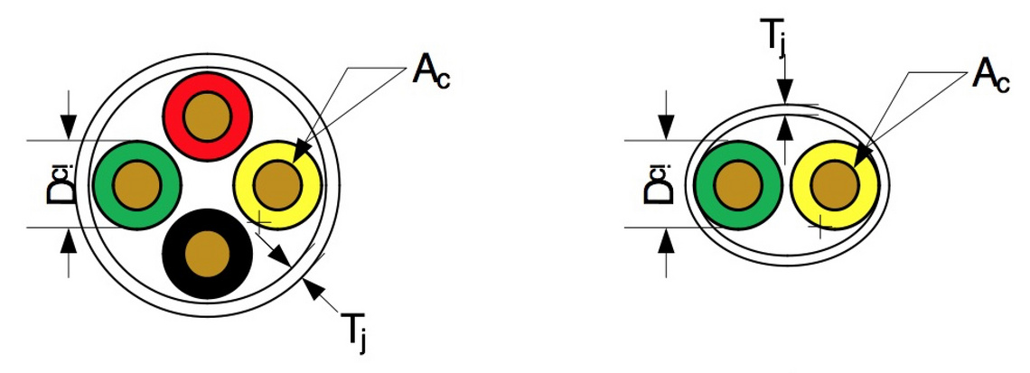
1. unshielded twisted quad
2. unshielded twisted pair
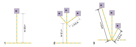
1. Simple stub
2. Compound stub
3. Multiple splice
TPPL is quite simple
TPPL is quite simple: the bus termination is made with a passive resistor of 120 Ohms (split configuration is also valuable), the TPPL IBBC is actually a sort of relay disconnecting the resistor when an implement is attached. There’s no TBC circuit by reducing the bus line into just CAN-H and CAN-L twisted wires. The twisting step is also a parameter which is quite important but some degree of freedom is left to manufactures: allowed value range is reported in the standard.
Moreover, a bunch of new chances for the network topology design have been introduced. Firstly, the bus stub length has been increased to 3m. Secondly new types of connection are now available to designers: multiple stub and multiple splice. The compound stub refers to a node on the bus from where up to three stubs branches out.
The multiple splice is a stub ending with a star-like topology. All of these new ways to connect devices to the bus give to engineers a lot of additional flexibility in bus design which drives to more rational topologies with a reduction of required harnesses. On the other hand, those connection types are to be used carefully and with some constraint in order to avoid signal reflection or noise on the bus. Engineers must take care of those possible issues.
All the featured mentioned above translate into a reduction of costs that can be considerable and, along with the additional flexibility end space saving, could make the TPPL very valuable for small tractors and implements.
If the features mentioned above are mostly related to the bus system, some news have been introduced also in the requirements for ECUs allowed to be connected to the network. Two new types are now allowed:
- ECU TYPE I WEAK: it has been introduced in order to guarantee higher immunity and better EMC performance. A Type I weak ECU is equipped with a high internal termination which is recommended to be implemented as a split-termination 750 Ω + 750 Ω with a 47 nF capacitor coupled with ECU_GND. The total number of Type I WEAK ECUs used on a single machine shall not exceed 3 units, and they are intended to be used where the risk for signal degradation can happen (i.e. long stubs or complex bus topologies)
- ECU TYPE II: includes an internal TPPL bus termination. It can be very useful on small tractors, for front bus termination, or on a implement with no requirements for daisy chain configuration.
The TPPL IBBC is identical to the one for TQPL in terms of pinout. The differences are to be found in the circuitry, due to the lack of active termination and TBC which are substituted by the circuitry for the passive termination. In order to solve possible problems in backward compatibility, the TBC_PWR pin of the TPPL IBBC is powered via ECU_PWR coupled with a fuse, while the TBC_RTN is connected to ECU_GND.
That allows to connect “legacy” ISOBUS implement to a TPPL based tractor with no electrical issues. Vice versa, also a TPPL implement can be attached to a “legacy” ISOBUS tractor: it just doesn’t use TBC related pins.
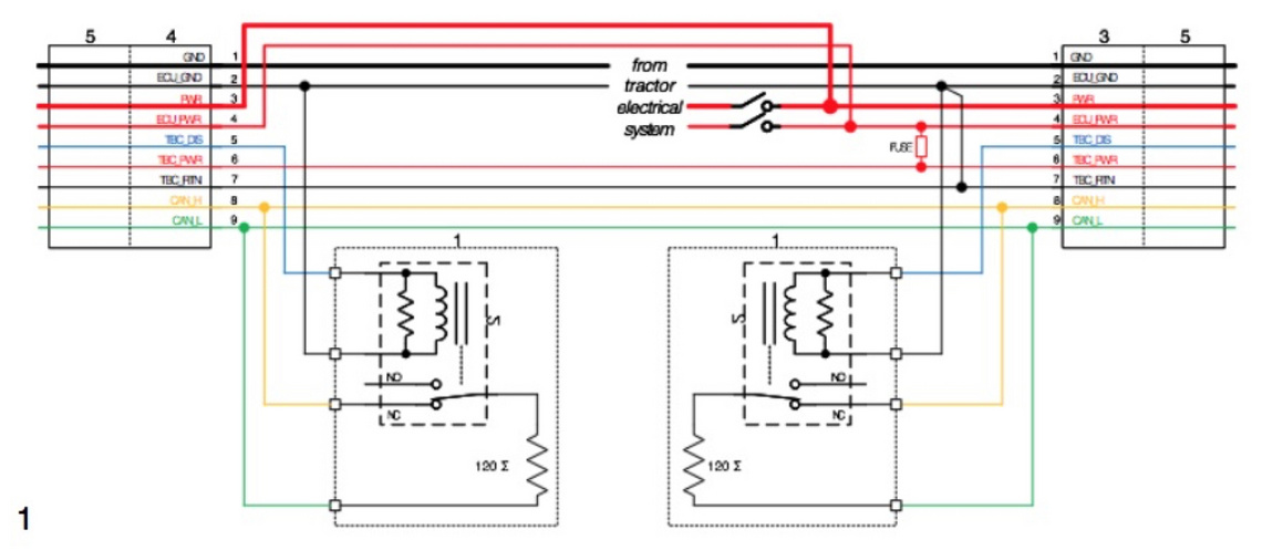
1. Example of TPPL bus.
The AEF hardware test protocol update for the TPPL are now discussed in AEF PT01 and will be available very soon. This allows manufacturers to start developing their TPPL based machines and components with a new level of flexibility and money savings. This will bring ISOBUS even more widely available, making it valuable for applications in vineyard, orchards and horticulture; environment where usually the cost and space requirements for “legacy” ISOBUS systems were a barrier to the market.